20 Image Sampling and Aliasing
20.1 Introduction
In nature, most of the signals we measure (sound, light, etc.) are defined over continuous domains (time, space, etc.). In order to process them with computers, we need to transform the continuous domain into a discrete one. Sampling is the process of transforming a continuous signal into a discrete one.
We need to study the following questions: What are the possible sampling patterns to sample a signal? How can we characterize the loss of information? And how do we reduce artifacts?
Understanding how information is transformed when we convert a continuous signal into a discrete signal is important because we often have to optimize two competing factors:
- Maximize the amount of available information. This requires as many samples as possible.
- Minimize the computational cost and memory requirements. This implies that we want to minimize the number of samples we collect.
In this chapter, we will be dealing with continuous and discrete signals and their corresponding Fourier transforms.
Let’s consider a one-dimensional (1D) continuous time signal \(\ell (t)\) and its sampled version \(\ell [n] = \ell(n T_s)\), where \(T_s\) is the sampling period. Intuitively, it is clear that in this sampling process, some information will get lost. If no information was lost, then we should be able to recover the continuous signal \(\ell (t)\) from its sampled version \(\ell [n]\) by doing some kind of interpolation. One way of ensuring that information is not lost is to decrease \(T_s\), which will result in a more accurate approximation of the continuous signal \(\ell (t)\) at the expense of the amount of memory needed to store \(\ell [n]\). Decreasing \(T_s\) will also result in an increase in the computational cost of processing the signal \(\ell [n]\). Therefore, it is important to choose the appropriate \(T_s\). Understanding the sampling process and how to reconstruct the continuous signal is necessary as it will allow us to find the optimal sampling parameters.
20.2 Aliasing
Let’s first look at one example to get a sense of the type of issues that might arise when discretizing a signal. Consider the continuous signal with the form \(\ell (t)=\cos (wt)\) with \(w=18\pi\), shown in Figure 20.1. The period of this signal is \(T=2 \pi / w = 1/9\) (there are nine periods in the interval \(t \in \left[0, 1 \right]\)).
We now build a discrete signal by sampling with a period of \(T_s=1/11\), which results in the discrete signal \(\ell [n] = \ell(n T_s)\) (there are 11 samples in the same interval \(t \in \left[0, 1 \right]\)). This could seem enough because there are more samples than periods. However, the samples of the discrete signal, \(\ell [n]\), are shown here (Figure 20.2):
If we now want to reconstruct the original continuous signal from its samples \(\ell [n]\), there are many possibilities because the samples do not constrain what happens between samples. Therefore, we will need to make some assumptions about the continuous signal. In the absence of any other prior information, we will assume that the most likely signal is the slowest and smoothest signal (we will make this assumption more precise later). Therefore, our preferred interpolation will be the one shown in red in the following plot:
The plot above shows the superposition of the original signal before sampling and the reconstructed one after sampling (in red). Both signals perfectly pass through the same samples. Under the slow and smooth prior, the samples seem to correspond to a cosine function with a lower frequency (in this example \(T=1/2\)) than the input (which had \(T=1/9\)).
It is important to mention that there is nothing special about how the parameters have been chosen for this example. Many different parameter choices would have yielded the same qualitative behavior. This confusion of frequencies is called aliasing.
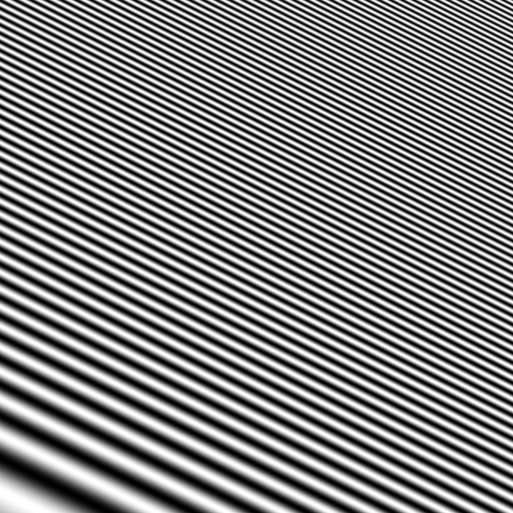
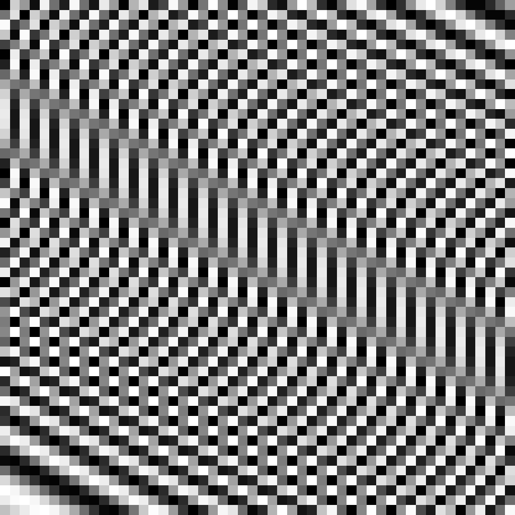
Let’s now look at an example in two dimensions (2D). As a concrete example, let’s consider the 2D signal shown in Figure 20.4 (a). This 2D signal is a continuous function in the spatial domain defined as \(\ell (x,y) = \cos (w (x+2y))\) and with a frequency, \(w\), which also varies with location following \(w = x+2y\). That is \(\ell (x,y) = \cos \left( (x+2y)^2 \right)\). The image shows a set of diagonal waves with a changing frequency starting slow at the bottom left and becoming faster and faster as we approach the top-right corner.
In order to store this continuous image on a computer, we need to sample it and convert it into a discrete image, \(\ell [ n,m ]\). Figure 20.4 (b) shows the resulting sampled image when the sampling rate is chosen so that it results in an image size \(52 \times 52\) pixels. The first thing to note is that the resulting image keeps very little similarity to the original signal. Only the bottom-left corner of the image looks anything like the continuous signal. As we move toward the right, the image changes the dominant orientation and the frequency becomes slow again.
Our perception seems to follow the slow and smooth assumption [1]. We have a prior towards smooth and slow trajectories and textures. In the presence of noise, or missing information, our visual system will tend to follow the prior.
20.3 Sampling Theorem
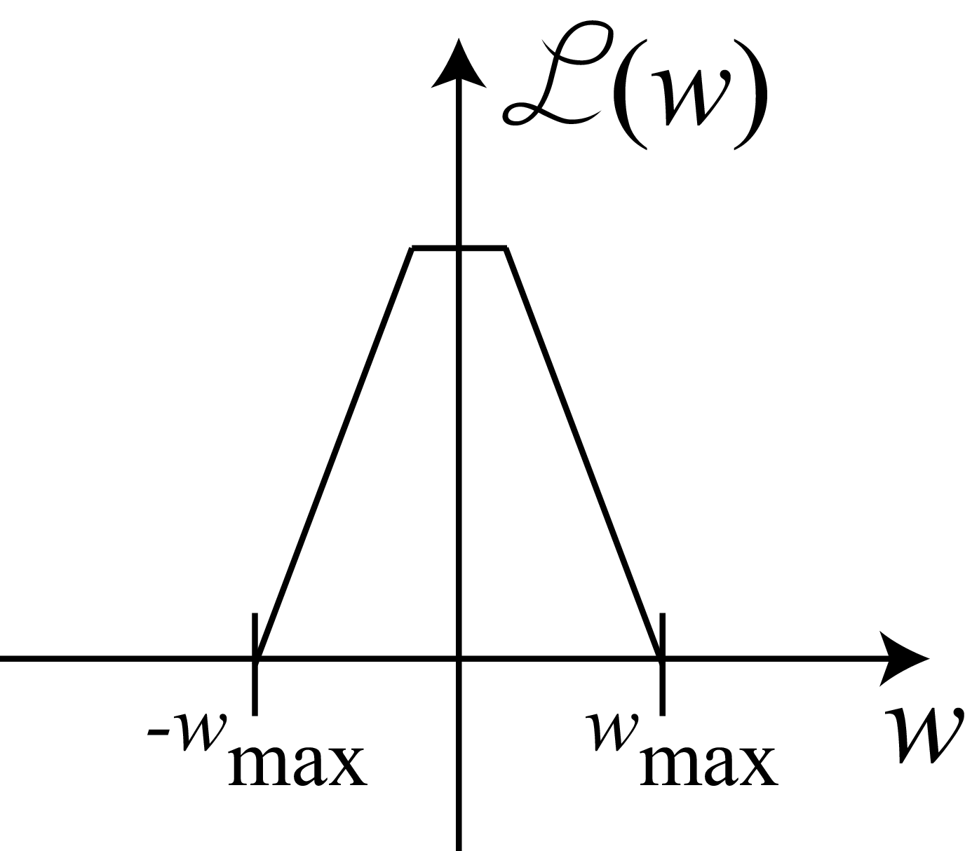
Let’s start by considering a band-limited signal \(\ell (t)\). A band-limited signal is a signal with no spectral content above a frequency \(w_{max}\). An example of a band-limited signal is a signal with the following Fourier transform:
The sampling theorem (also known as Nyquist theorem) states that for a signal to be perfectly reconstructed from a set of samples (under the slow and smooth prior), the sampling frequency \(w_s = 2 \pi /T_s\) has to be \(w_s > 2w_{max}\) when \(w_{max}\) is the maximum frequency present in the input signal [2].
The same theorem can be stated in terms of periods: the sampling period, \(T_s\), has to be \(T_s < T_{min} / 2\), i.e., smaller than half of the period of the highest frequency component, \(T_{min} = 2 \pi /w_{max}\). Note that our previous example did not satisfy the Nyquist condition.
In this book, we use the radian frequency for continuous signals, \(w = 2 \pi f\), where \(f\) is the hertz frequency. For a sinusoidal wave of period \(T\) seconds, its frequency is \(w=2\pi / T\).
One way of characterizing the sampling process is achieved by analyzing the relationship between the Fourier transform of the continuous and discrete signals. There are many ways of finding the relationship between the two Fourier transforms. Here we will describe the most common one.
20.3.1 Modeling the Sampling Process
First, let’s use the following notation. Let’s denote as \(\ell(t)\) the continuous signal and \(\ell_s [ n ] = f(nT_s)\) the discrete signal obtained by sampling the continuous signal. We are interested in knowing how the Fourier transform of \(\ell_s [ n ]\) is related to the Fourier transform of \(\ell(t)\).
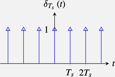
Let’s start writing a model of the sampling process by defining a very special signal: the delta train distribution (also known as the impulse train or Dirac comb). The delta train, \(\delta_{T_s}(t)\), is a periodic signal, with period \(T_s\), composed of delta impulses centered at times \(nT_s\). It is defined as:
\[ \delta_{T_s}(t) = \sum_{n=-\infty}^{\infty} \delta(t-n T_s) \]
When \(T_s = 1\), the delta train has the following shape:
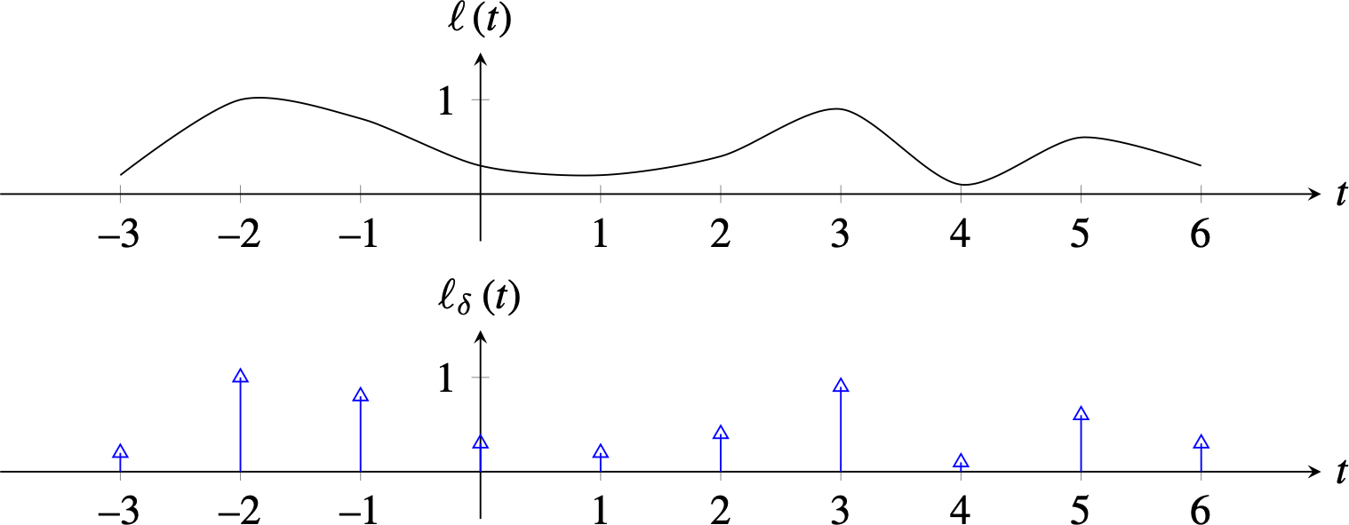
The delta train can be used to model the sampling process. Remember the sampling property of the delta distribution \(\ell (t) \delta (t-a) = \ell(a)\). If we multiply a function, \(\ell(t)\), by the delta train, \(\delta_{T_s}(t)\), we obtain its sampled version at times \(nT_s\), which we will denote as \(\ell_{\delta} (t)\):
\[ \ell_{\delta} (t) = \ell(t) \delta_{T_s}(t) = \ell(t) \sum_{n=-\infty}^{\infty} \delta(t-n T_s) = \sum_{n=-\infty}^{\infty} \ell_s [ n ] \delta(t-n T_s) \]
The two plots in Figure 20.7 show a continuous function and its sampled version using the delta train.
The delta-sampled function \(\ell_{\delta} (t)\) is a very special function that contains the same amount of information as the discrete signal \(\ell_s [ n ]\) but that is defined over the continuous domain \(t\). In fact, the Fourier transform of \(\ell_{\delta} (t)\) and \(\ell_s [ n ]\) are closely related as we will show next.
As \(\ell_s [ n ]\) is an infinite-length discrete signal, its discrete Fourier transform (DFT) is:
\[ \mathscr{L}_s(w) = \sum_{n=-\infty}^{\infty} \ell_s [ n ] \exp{(-jwn)} \]
and the continuous Fourier transform of \(\ell_{\delta} (t)\), an infinite-length continuous signal, is:
\[ \begin{split} \mathscr{L}_{\delta} (w) &= \int_{n=-\infty}^{\infty} \ell_{\delta} (t) \exp{(-jwt)} dt \\ & = \int_{n=-\infty}^{\infty} \ell(t) \sum_{n=-\infty}^{\infty} \delta(t-n T_s) \exp{(-jwt)} dt \\ & = \sum_{n=-\infty}^{\infty} \int_{n=-\infty}^{\infty} \ell(t) \delta(t-n T_s) \exp{(-jwt)} dt \\ & = \sum_{n=-\infty}^{\infty} \ell(n T_s) \exp{(-j w n T_s)} \end{split} \]
Comparing the equations, we see that both Fourier transforms are identical up to a scaling factor:
\[ \mathscr{L}_s(w) = \mathscr{L}_{\delta} \left( \frac{w}{T_s} \right) \]
In practice, we will never directly work with the signal \(\ell_{\delta} (t)\), but it is a convenient construction to understand how information is transformed during the sampling process. Understanding how the sampling rate \(T_s\) affects \(\ell_{\delta} (t)\) is equivalent to understanding the effect that the sampling rate has on \(\ell_s [ n ]\).
20.3.2 Sampling in the Fourier Domain
Now that we have seen that \(\ell_{\delta} (t)\) and the discrete signal \(\ell_s [ n ]\) have similar Fourier transforms, let’s compute the Fourier transform of \(\ell_{\delta} (t)\). Note that \(\ell_{\delta} (t)\) is the product of two continuous signals. The first term is the continuous signal \(\ell(t)\), and the second term is a function composed of impulses placed at regular time instants \(\delta(t-n T_s)\). We can compute the continuous Fourier transform of \(\ell_{\delta} (t)\) as the convolution of the Fourier transforms of \(\ell(t)\) and \(\delta_{T_s}(t)\).
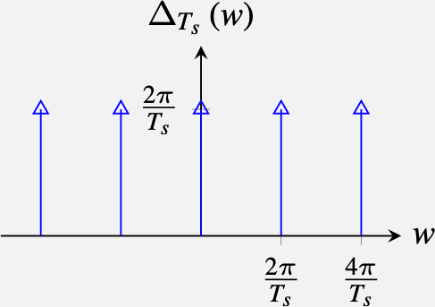
The Fourier transform of a delta comb is:
\[ \begin{split} \Delta_{T_s} (w) &= \int_{-\infty}^{\infty} \delta_{T_s}(t) \exp \left(-jwt\right) dw \\ & =\sum_{n=-\infty}^{\infty} \int_{-\infty}^{\infty} \delta(t-n T_s) \exp \left(-jwt\right) dw \\ & =\sum_{n=-\infty}^{\infty} \exp \left(-jwnT_s\right) \\ & = \frac{2\pi}{T_s} \sum_{k=-\infty}^{\infty} \delta \left(w-k \frac{2 \pi}{T_s} \right) \end{split} \]
Deriving the last step is a bit involved, and we invite the readers to work out the details. The result is that the Fourier transform of an impulse train is also an impulse train but with a displacement in frequency between impulses that grows when the spacing in time decreases:
\[ \delta_{T_s}(t) \xrightarrow{\mathscr{F}} \delta_{\frac{2 \pi}{T_s}}(w) \]
Therefore, the continuous Fourier transform of \(\ell_{\delta} (t)\) can be written as:
\[ \mathscr{L}_{\delta} (w) = \mathscr{L}(w) \circ \frac{2\pi}{T_s} \sum_{k=-\infty}^{\infty} \delta \left(w-k \frac{2 \pi}{T_s} \right) = \frac{2\pi}{T_s} \sum_{k=-\infty}^{\infty} \mathscr{L} \left(w-k \frac{2 \pi}{T_s} \right) \]
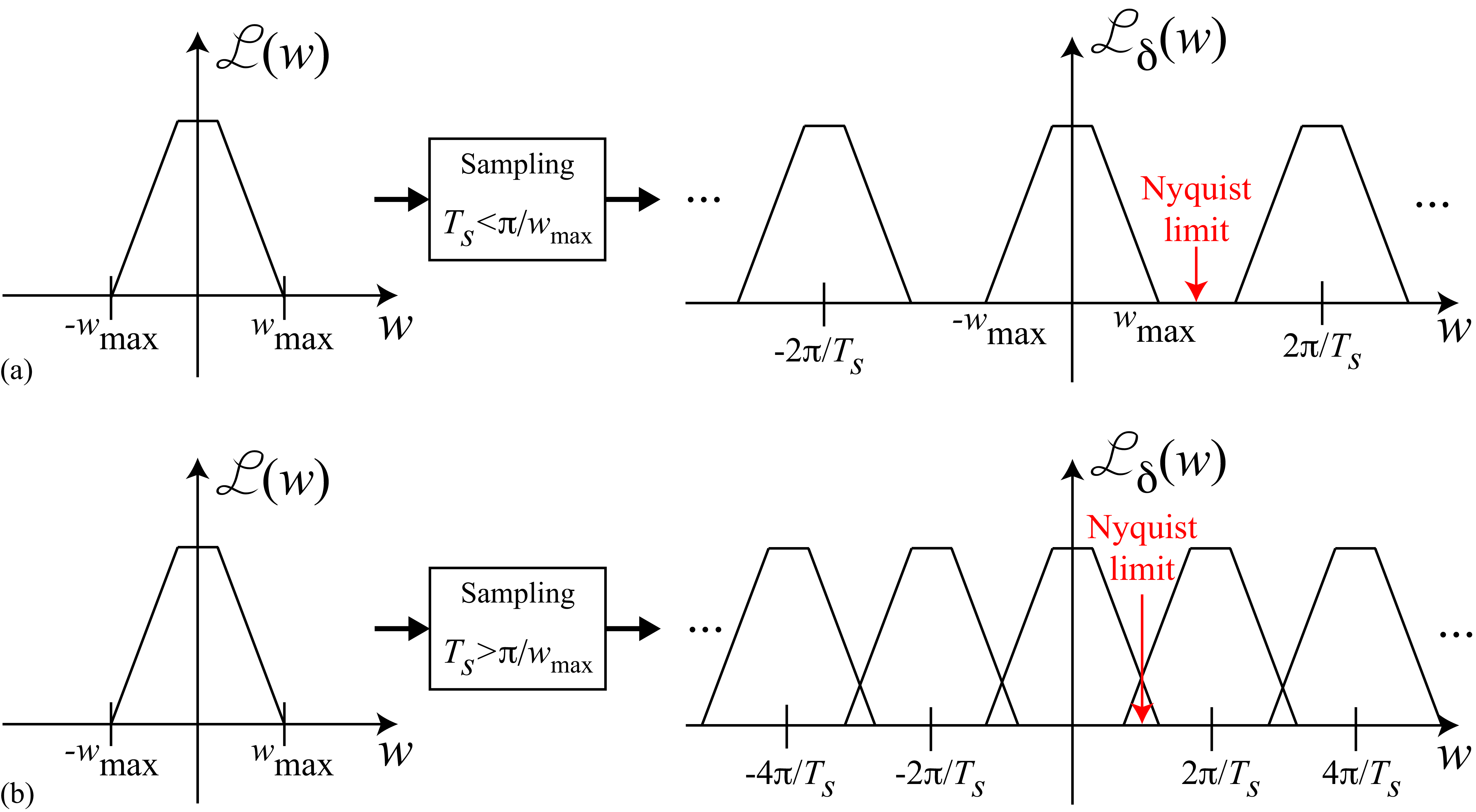
where \(\mathscr{L}(w)\) is the Fourier transform of \(\ell(t)\). This equation shows that \(\mathscr{L}_{\delta} (w)\) is built as an infinite sum of translated copies of \(\mathscr{L}(w)\), as shown in Figure 20.8 (a). Each copy is centered on \(k \frac{2 \pi}{T_s}\). If \(T_s\) is small (i.e., if we sample very fast), then those copies will be far away from each other (Figure 20.8 (a)). But if we have few samples and \(T_s\) is large, those copies will get very close and will start mixing with each other (Figure 20.8 (b)). High-frequency content in \(\mathscr{L}(w)\) will affect the low-frequency content of \(\mathscr{L}_{\delta} (w)\), and this is exactly what produces aliasing.
The Nyquist limit is reached when the maximum frequency, \(w_{max}\), with spectral content in \(\mathscr{L} (w)\) overlaps with its translated copy. This overlap occurs when the sampling period, \(T_s\), is \(T_s > \pi/w_{max}\). To avoid aliasing, the sampling period has to be shorter than \(\pi/w_{max}\).
20.4 Reconstruction
The reconstruction process consists of recovering a continuous signal from its samples by interpolation. In this section, we will study what the ideal interpolation scheme is and what other practical interpolations exist.
20.4.1 Ideal Reconstruction
When the Nyquist condition is satisfied, we know that it is possible to reconstruct the original continuous signal from the samples. We just need to apply a box filter that has a constant gain for all the frequencies inside \(w \in \left[-\pi / T_s, \pi / T_s \right]\), and 0 outside. The phase of the filter should be zero. That is,
\[ H(w) = \begin{cases} \frac{T_s}{2\pi} & \quad \text{if } w \in \left[-\pi / T_s, \pi / T_s \right]\\ 0 & \quad \text{otherwise }\\ \end{cases} \tag{20.1}\]
The impulse response of such a filter is \(h(t) = \text{sinc} (t/T_s)\) where the sinc function is:
\[ \text{sinc} (t) = \frac{\sin (\pi t)}{\pi t} \]
The sinc function (Figure 20.9) is an infinite-length continuous signal that has its maximum at the origin, \(\text{sinc} (0)=1\), it is symmetrical, \(\text{sinc} (t) = \text{sinc} (-t)\), and it is a sinusoidal wave with a period of 2 that decays in amplitude at a rate \(1/t\).
When no other prior information is available about the function \(\ell(t)\), and under the slow and smooth prior, this is the optimal reconstruction in terms of the L2 norm:
\[ \begin{split} \text{sinc} (t/T_s) & = \text{argmin}_{h(t)} \int \left( \ell(t) - \ell_{\delta} (t) \circ h(t) \right)^2 dt \\ & = \text{argmin}_{h(t)} \int \left( \mathscr{L}(w) - \mathscr{L}_{\delta} (w) H(w) \right) ^2 dw \end{split} \]
Then the function, \(\ell_{\delta} (t)\), that best approximates the input signal from its samples is:
\[ \widetilde \ell(t) = \ell_{\delta} (t) \circ \text{sinc} (t) = \sum_{n=-\infty}^{\infty} \ell_s[n] \text{sinc} \left(\frac{t-nT_s}{T_s} \right) \]
where \(\widetilde \ell(t)\) is the reconstructed signal from the samples \(\ell_s[n]\). The plot in Figure 20.10 shows how the linear superposition of all the scaled and shifted sincs produces a smooth interpolation of the sampled function. Note how the zero crossings of each sinc coincide with the sample locations.
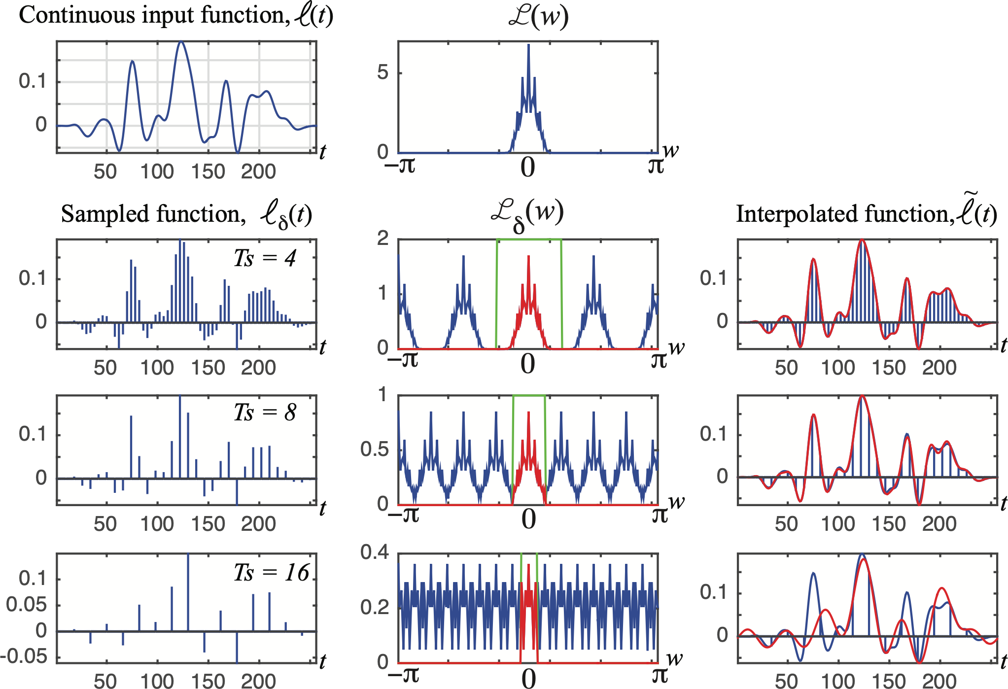
Figure 20.11 illustrates how the reconstruction degrades as a function of the sampling rate. In this example, there is one band-limited input signal (i.e., there is a frequency, \(w_{max}\), for which the magnitude of the Fourier transform is zero for all frequencies above \(w_{max}\)). When we sample this signal with a sampling period of \(T_s = 4\) s, in its FT we see replicates of the \(\mathscr{L}(w)\) centered around \(\pi/2\). With \(T_s=8\) s, the replicates appear centered around \(\pi/4\) and they start touching. Note that \(T_s=8\) is slightly above the Nyquist’s limit and some aliasing will exist. For \(T_s=16\), aliasing is severe and information will be lost, making it impossible (without any additional prior information) to reconstruct the continuous function from its samples.
A signal cannot be simultaneously time-limited and frequency band-limited. For any time-limited signal (i.e., a signal that is defined inside an interval \(t \in \left[a,b \right]\) and is zero outside), the Fourier transform is not band-limited.
All the derivations extend naturally to 2D because all the functions are separable along the two spatial dimensions. In two dimensions, the ideal interpolation function is:
\[ \text{sinc} (x,y) = \frac{\sin (\pi x)}{\pi x} \frac{\sin (\pi y)}{\pi y} \]
We will discuss the 2D case a bit more in detail later as sampling images opens the door to different sampling strategies beyond simply adjusting the sampling rate.
20.4.2 Approximate Reconstruction with Local Kernels
One disadvantage of the ideal reconstruction is that the \(\text{sinc}\) function has infinite support, which means that to interpolate each instant, we need to linearly combine all the samples \(\ell [n]\). Sometimes it is better to have a local reconstruction that only depends on the nearby samples.
Indeed, there are other possible reconstructions that are not optimal in terms of the L2 norm, but that only require local computations.
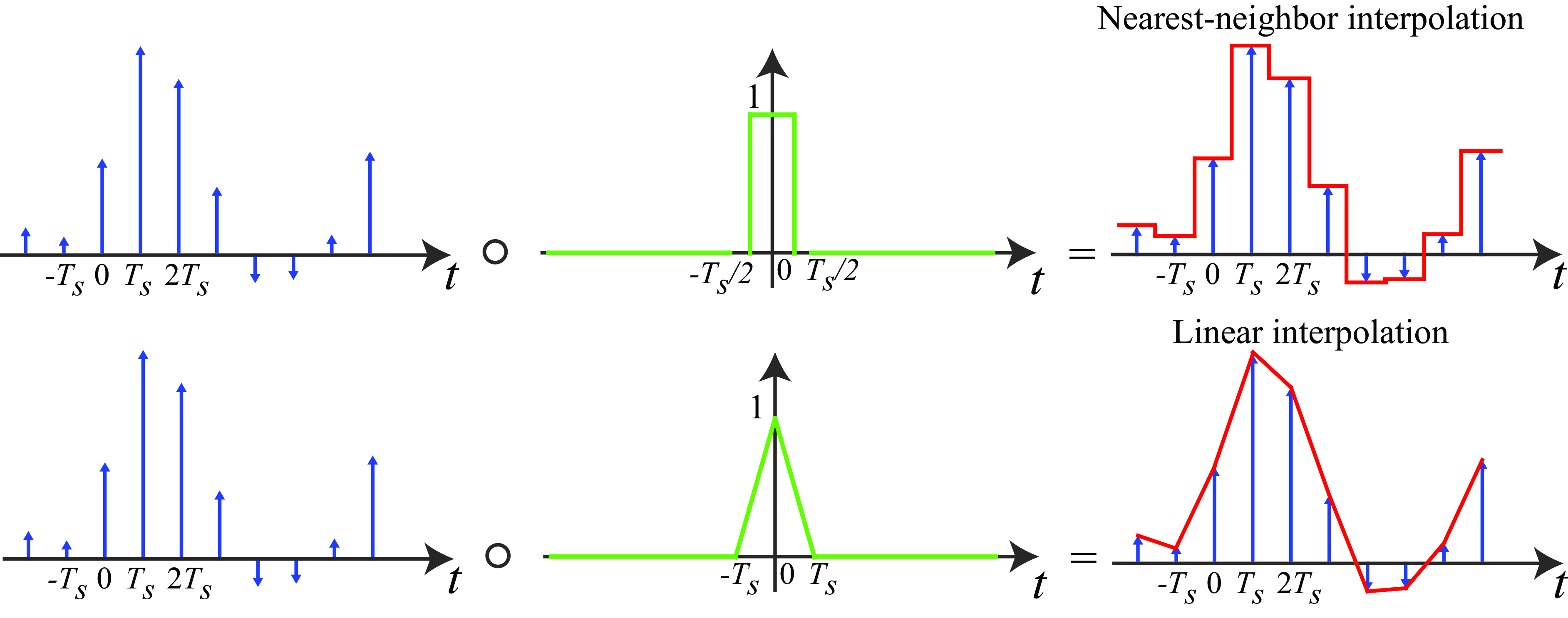
In 1D, some of the most popular interpolation kernels are nearest interpolation and linear. Nearest interpolation consists of assigning to each time instant the value of the nearest sample in time. Linear interpolation consists of interpolating linearly between two consecutive values.
All of them can be written as a linear convolution with a kernel \(h(t)\) as shown in Figure 20.12:
The nearest neighbor interpolation is the result of the convolution of \(\ell_\delta (t)\) with a box of width \(T_s\). In the linear interpolation, the interpolation kernel \(h(t)\) is a triangle of width \(2T_s\).
The convolution of two box filters of width \(T_s/2\) is a triangle of length \(T_s\).
Lanczos-1 interpolation consists of using as kernel only the central lobe of the sinc function. This provides an interpolation that is smooth using only a local neighborhood. Other interpolation methods such as cubic interpolation can also be written as convolutions. ## A Family of 2D Spatial Samplings
Let’s now analyze what happens when sampling 2D signals to form discrete images. In 2D, things get more interesting. If we have a continuous image \(\ell (x,y)\) we can sample it using a rectangular grid as \(\ell_s [n,m] = \ell (nT_x, mT_y)\). We can do a very similar analysis to the one we just did for the 1D case. But in 2D, we can have more interesting sampling patterns. For instance, we could define the discrete image as:
\[ \ell_s [n,m] = \ell (an+bm, cn+dm) \]
where \(a,b,c,d\) are constants. For instance, if \(a=T,b=0,c=0,d=T\), then we will have a regular rectangular sampling. But we could have other patterns. For instance, if we set \(a=T_1,b=-T_2 / 2,c=0,d=T_2\), then we obtain a hexagonal sampling. We can also place the samples at random locations (irregular sampling). Figure 20.13 shows different sampling patterns.
Now we can ask the following question: What is the optimal 2D sample arrangement given a fixed number of samples? What we want is to choose the sample arrangement that will allow the best reconstruction of the input continuous signal from a fixed number of samples. As we did with the 1D case, we can answer this question by studying the relationship between the Fourier transform of the continuous signal and the sampled one, which will reveal how aliasing happens and what sampling pattern minimizes it.
We model sampling by multiplying the continuous image by a delta train in 2D:
\[ \ell_{\delta} (x,y) = \ell (x,y) \sum_{n=-\infty}^{\infty} \sum_{m=-\infty}^{\infty} \delta (x- an-bm, y - cn-dm) \]
We can simplify the notation by encoding the position as vectors, \(\mathbf{x} = (x,y)^T\), \(\mathbf{n} = (n,m)^T\), and \(\mathbf{A}\) is the matrix:
\[ \mathbf{A} = \left[ \begin{array}{cc} a & b\\ c & d \end{array} \right] \]
where the 2D delta train can be written using vector notation for the continuous spatial coordinates:
\[ \delta_{\mathbf{A}}(\mathbf{x}) = \sum_{\mathbf{n} \in \mathbb{Z}^2} \delta \left( \mathbf{x} - \mathbf{A} \mathbf{n} \right) \]
The continuous Fourier transform of this delta train can be done by applying a change in variables and then using a similar procedure as the one followed in the 1D case. The result is:
\[ \Delta_{A} (\mathbf{w}) = \frac{(2 \pi)^2}{|\mathbf{A}|} \sum_{\mathbf{k} \in \mathbb{Z}^2} \delta \left( \mathbf{w} - 2 \pi \mathbf{A}^{-1} \mathbf{k} \right) \]
Therefore, the Fourier transform of the sampled signal \(\ell_{\delta} (x,y)\) is:
\[ \mathscr{L}_{\delta} (\mathbf{w}) = \frac{(2 \pi)^2}{|\mathbf{A}|} \sum_{\mathbf{k} \in \mathbb{Z}^2} \mathscr{L} \left( \mathbf{w} - 2 \pi \mathbf{A}^{-1} \mathbf{k} \right) \tag{20.2}\]
Remember that for \(2\times2\) matrices, the inverse is easy to write:
\[ \mathbf{A}^{-1} = \frac{1}{|\mathbf{A}|} \left[ \begin{array}{cc} d & -b\\ -c & a \end{array} \right] \]
We can now check what happens with different sampling strategies. For instance, the 2D rectangular sampling simplifies to:
\[ \mathscr{L}_{\delta} \left(w_x, w_y \right) = \frac{(2 \pi)^2}{T^2} \sum_{k_1=-\infty}^{\infty} \sum_{k_2=-\infty}^{\infty} \mathscr{L} \left(w_x - \frac{2\pi}{T}k_1, w_y - \frac{2\pi}{T}k_2 \right) \]
This is similar to the 1D case. We leave it to the reader to write down the form of the hexagonal sampling.
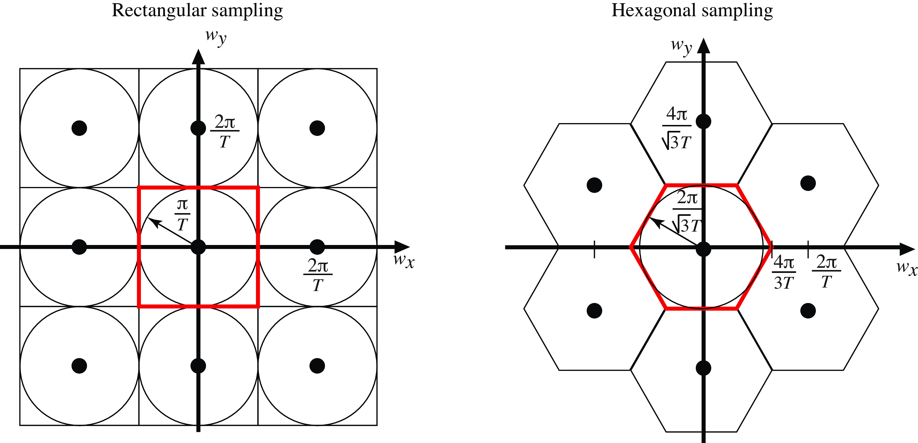
Figure 20.14 shows a sketch of the Fourier transforms of the rectangular and hexagonal samplings. The region delimited by the red polygon shows the region of valid frequencies. If the input signal only has spectral content within that region, then there will be no aliasing. The optimal sampling will be the one that makes that region as large as possible for a fixed number of samples.
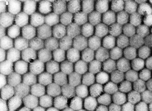
The optimal sampling strategy is the regular hexagonal sampling. This is not the sampling used in computer vision as all images are always represented on a rectangular grid, but a hexagonal sampling achieves an increase of around \(10\) percent in resolution for the same amount of samples. In fact, the distribution of photoreceptors at the center of the retina [3,4] closely resembles a hexagonal array over small patches, as shown in Figure 20.15.
Working with convolutional filters defined over a hexagonal grid is more efficient, and it can achieve better radial symmetry [5,6].
The analysis we have presented in this chapter assumes signals of infinite length. However, images will have a finite size. The same results can be applied by extending the image to infinity with zero padding.
20.5 Anti-Aliasing Filter
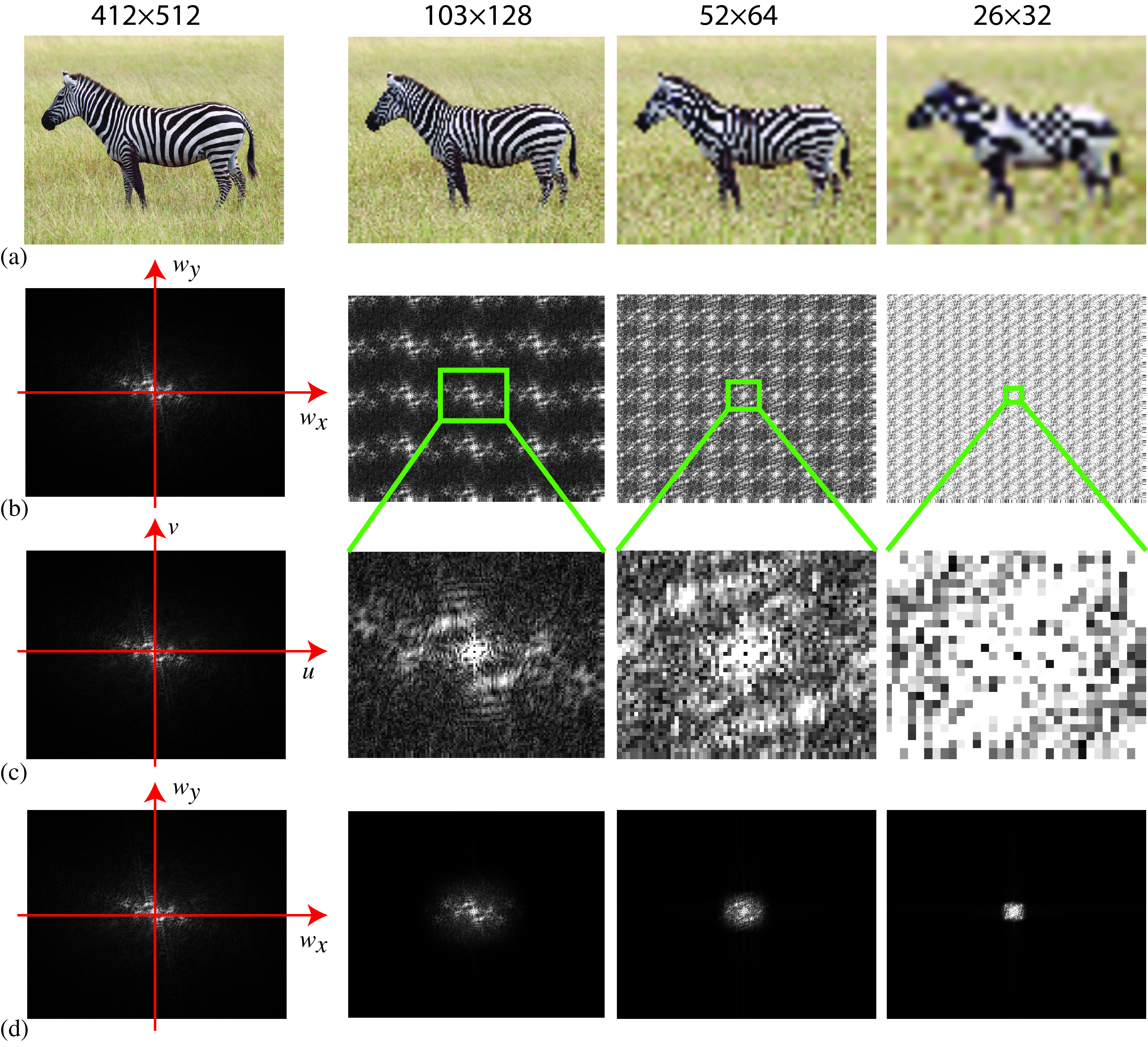
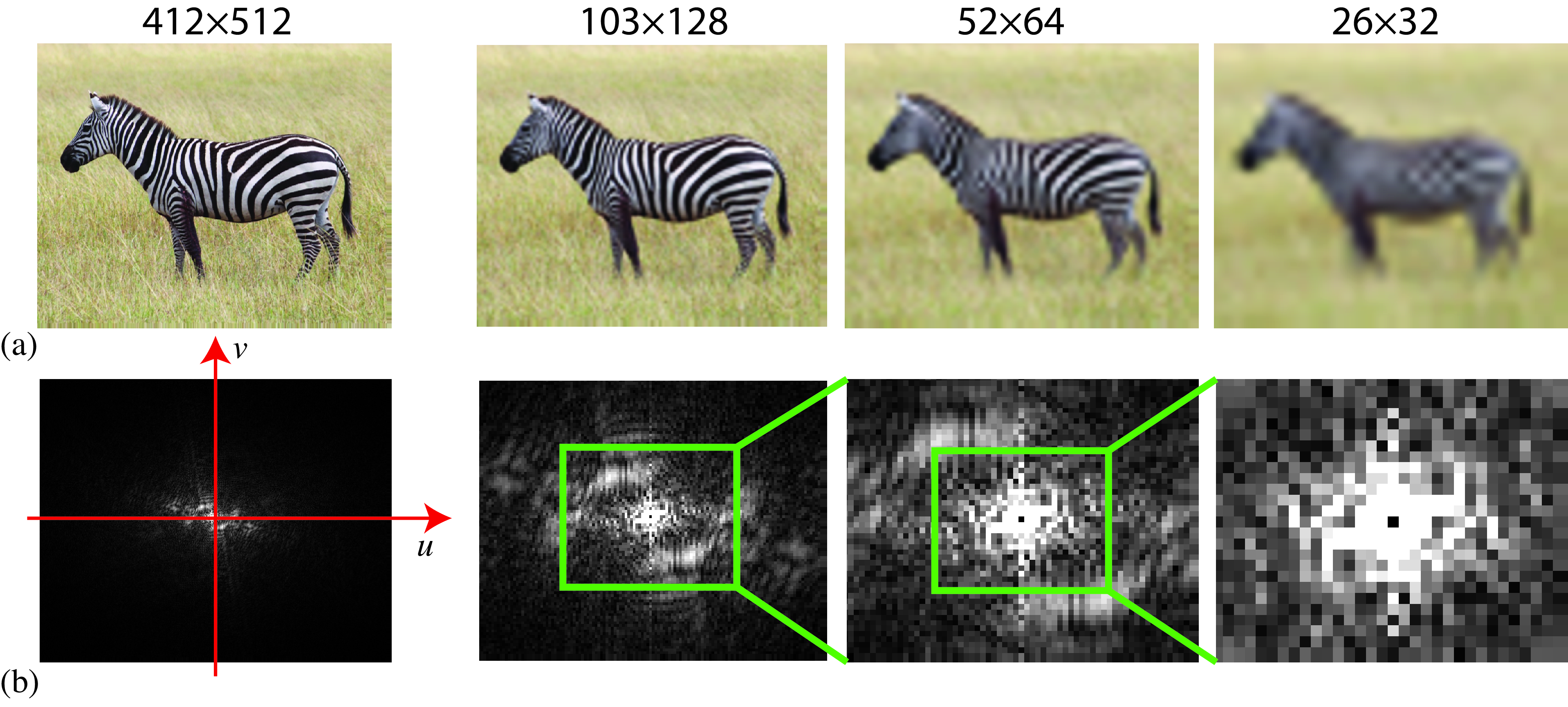
Sampling with the wrong frequency has interesting effects in 2D. Figure 20.16 (a) shows an example of a picture downsampled at different resolutions (412×512, 103×128, 52×64, and 26×32) and then reconstructed to the original resolution (412×512 pixels). For the figures, as we do not have access to the continuous image, we always work with sampled versions. But the original image is very high resolution and we can think of it as being the continuous image.
The images in Figure 20.16 (a) show the effects of aliasing. The stripes on the zebra’s body change orientation as we downsample them. And for the lowest resolution image, it is even hard to recognize the animal as being a zebra. Figure 20.16 (b) shows what happens with the image Fourier transform when we multiply the image with the delta train, with one every four samples along each dimension (second column of Figure 20.16 (b)). Figure 20.16 (c) shows the magnitude of the DFT of the sampled image (it corresponds to the region inside the green square in Figure 20.16 (b)). The DFT changes substantially, due to aliasing, from one resolution to the next one.
In order to reduce aliasing artifacts, we need to filter the continuous signal with a low-pass filter to make it band-limited. Then we will be able to sample it, avoiding high-spatial frequencies that interfere with the low-frequency content of the image. The anti-aliasing filter will not prevent the loss of information contained in the high spatial frequencies. Figure 20.17 (a) shows the reconstructed images at different resolutions when an anti-aliasing filter is applied before sampling. Each resolution requires a different filter. The anti-aliasing filter can be a box filter like in Equation 20.1 with the support equal to the green region in Figure 20.16 (b).
20.6 Spatiotemporal Sampling
Spatiotemporal sampling can be studied with the tools we have already seen. In particular, Equation 20.2 can explain sampling in the \(N\)-dimensional case. Temporal aliasing is responsible for the typical illusion in which we see wheels or fans changing the sense of rotation in movies. To avoid those artifacts, it is important to apply an anti-aliasing filter as before.
The most common type of spatiotemporal sampling is regular sampling: here, all the pixels are sampled in a regular spatial 2D grid and at regular time instants in which all the pixels are exposed simultaneously. This is also called global shutter mode.
In many cameras (DSLRs, mobile phones, etc.), the most commonly used sampling is the rolling shutter mode. Here, every row in the image is sampled simultaneously. But different rows are sampled at different instants. This sampling mode allows for a faster sampling rate with current hardware implementations, but it can create spatial distortions in the image if the camera moves or when taking pictures of moving objects.
20.7 Concluding Remarks
Aliasing is a common artifact that appears whenever an image is captured by sampling a continuous light field. As we will discuss in the next chapter, aliasing also affects images whenever there is upsampling or downsampling. Therefore, understanding how aliasing introduces artifacts and the best way to avoid it is an important skill.
However, aliasing is not always bad and it might be possible to use aliasing to recover high-frequency content that would be otherwise lost. Superresolution algorithms can learn to extract, from the aliasing pattern, fine image details.
Also, when an image is encoded by multiple channels, aliasing in one channel does not mean that the information is lost because multiple channels could contain complementary information that allows the recovery of high-resolution details.


